Cosmetic Packaging
Display Packaging
CBD Packaging
Retail Packaging
Product Packaging
Cigarette Packaging
Candle Packaging
Soap Packaging
Chocolate Packaging
Vape Packaging
Food Packaging
Gift Packaging
Bakery Packaging Boxes
Pizza Packaging
Bottle Packaging
Garments Packaging
Custom Printed Bags
Christmas Packaging
Toy Packaging
Cereal Packaging
Jewelry Packaging
Apparel Packaging
Shipping Packaging
Custom Pre Roll Boxes
Dispenser packaging
Eco Friendly Packaging
Custom Health Packaging
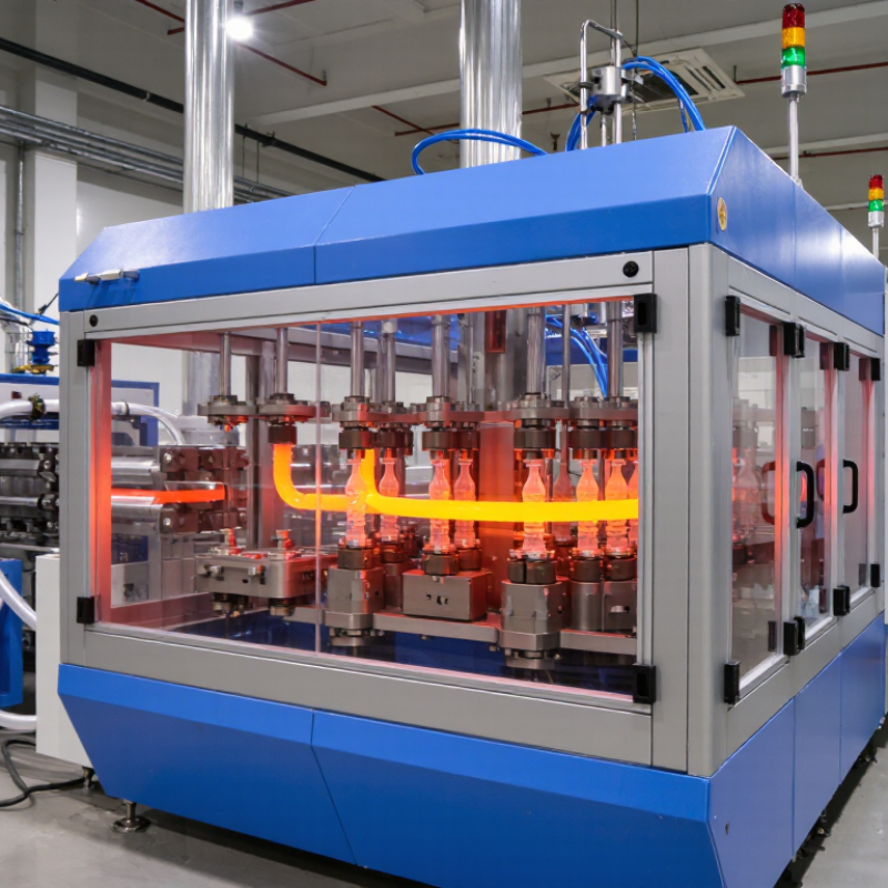
Pharmaceutical PackagingA Blow Maker is an industrial machine used to produce hollow plastic products, including bottles, containers, and technical housings. It shapes heated plastic inside a mold. The process may use extrusion blow molding, injection blow molding, or stretch blow molding. Each method suits different materials, shapes, and production targets.
The working cycle begins when plastic pellets enter a heated barrel. Controlled heat softens the material into a uniform melt. In extrusion systems, the machine forms a hollow tube called a parison. A mold closes around it. Compressed air then expands the parison against the mold’s inner walls. The plastic cools through channels inside the mold. After opening, the finished container moves toward trimming and inspection. Small temperature changes can affect wall thickness.
Understanding this process requires more than watching the machine operate. Experienced technicians check air pressure, mold alignment, cooling-water flow, and cycle timing. They also compare samples with approved dimensions and appearance standards. Manufacturer manuals and recognized workplace safety requirements should guide setup and maintenance. A clean air system matters. Moisture or oil can damage surfaces and reduce product quality.
It sounds simple.
In practice, it is not always predictable. Uneven cooling may create thin spots, distortion, or weak seams. Material grade, humidity, and mold design can change the result. This guide explains the equipment clearly, while recognizing that real production conditions vary. Reliable operation depends on trained personnel, documented settings, and careful inspection rather than guesswork.
A blow maker machine is industrial equipment used to form hollow plastic products. It uses heat, air pressure, and a shaped mold. Common outputs include bottles, containers, tanks, and protective packaging. The term “blow maker” is not perfectly precise. Manufacturers usually mean a blow molding machine. That distinction matters when comparing equipment specifications and production methods.
In a typical extrusion blow molding process, plastic pellets enter a heated barrel. A screw melts and pushes the material through a die. This creates a soft tube called a parison. The mold closes around it. Compressed air expands the parison against the mold walls. After cooling, the mold opens and releases the finished container. On production floors, small temperature changes can affect wall thickness. That detail is easy to underestimate.
Some machines use injection stretch blow molding for lightweight, clear containers. They first form a preform, then heat and stretch it inside a second mold. This method can improve strength and material distribution. Operators monitor air pressure, cooling time, mold alignment, and resin moisture. Poor settings may create thin corners, cloudy surfaces, or weak necks. Quality checks should include dimensions, weight, leak testing, and visual inspection. The process looks simple, but it is less forgiving than it appears.
A blow maker machine forms hollow plastic products, such as bottles and containers. It heats plastic material until it becomes soft and workable. The machine then shapes it with air pressure. Its performance depends on several connected parts, not one single unit.
The hopper stores plastic pellets before processing. An extruder moves and melts them through a heated barrel. The die head shapes the melted plastic into a tube called a parison. A mold then closes around the parison. Compressed air expands the plastic against the mold walls. The clamping unit keeps the mold firmly closed during forming. Cooling channels remove heat and help the product keep its shape. After opening, a trimming system removes excess plastic. Sensors and a control panel monitor temperature, pressure, timing, and mold position. Small setting errors can still cause thin walls or uneven finishes.
Tips: Check the hopper for contamination before production. Keep heating zones stable, and inspect air pressure regularly. Cooling water should flow evenly through each mold. In practical operation, operators often adjust timing by trial and measurement. This is not a weakness; different materials and shapes respond differently. Also, a clean die head matters. Residue can disturb the parison and create defects. Safety guards, emergency stops, and routine inspections should remain active at all times.
| Part or System | Main Function | How It Works | Typical Materials or Components | Important Operating Considerations |
|---|---|---|---|---|
| Material Hopper | Stores and feeds plastic resin into the machine. | Pellets are held above the extrusion or injection unit and enter the conveying system through a controlled opening. | Plastic pellets such as PET, HDPE, PP, or other process-compatible resins. | The resin should be clean, correctly identified, and dried when the material requires moisture removal. |
| Extruder or Injection Unit | Melts and prepares the plastic for forming. | A screw conveys plastic through heated zones, or an injection barrel pushes molten plastic into a preform mold. | Barrel, screw, heater bands, thermocouples, and drive motor. | Temperature profile, screw speed, residence time, and melt pressure affect material quality and consistency. |
| Heating System | Softens the plastic preform or parison to the required forming temperature. | Heating elements transfer controlled radiant or conductive heat while temperature sensors monitor different zones. | Infrared lamps, ceramic heaters, reflectors, temperature sensors, and cooling fans. | Uniform heating is essential for balanced wall thickness and stable container dimensions. |
| Parison or Preform System | Creates the initial plastic shape that will be expanded into the final product. | An extrusion machine produces a hollow parison, while an injection stretch blow machine uses a molded preform. | Molten tube, PET preform, die head, injection mold, or preform transfer mechanism. | Length, temperature, weight distribution, and neck geometry influence the finished container. |
| Mold | Defines the external shape and surface details of the product. | The mold closes around the parison or preform and provides the cavity into which the plastic is expanded. | Usually aluminum or steel mold halves, cavity surfaces, vents, cooling channels, and clamping faces. | Mold alignment, venting, cooling efficiency, and cavity finish affect appearance and dimensional accuracy. |
| Clamping Unit | Closes, holds, and opens the mold during the forming cycle. | A hydraulic, pneumatic, or servo-driven mechanism applies sufficient force to keep the mold closed during blowing. | Clamping plates, guide columns, toggle or linear mechanism, hydraulic cylinders, or servo actuators. | Clamping force must be high enough to prevent flash but controlled to avoid unnecessary mold wear. |
| Blow Pin or Blow Nozzle | Introduces compressed air into the hot plastic. | The nozzle seals against the preform or parison opening and delivers air that expands the plastic against the mold wall. | Blow pin, sealing surface, air valve, nozzle holder, and neck-support components. | Correct sealing, nozzle alignment, and air timing help prevent leaks, deformation, and incomplete forming. |
| Compressed-Air System | Provides the air used to stretch and form the container. | Compressed air passes through filters, regulators, valves, and piping before entering the mold cavity. | Compressor, air receiver, filters, pressure regulator, valves, and high-pressure lines. | Air pressure, flow rate, cleanliness, and moisture control directly influence cycle stability and product quality. |
| Stretch Rod | Stretches the preform lengthwise in stretch blow molding. | The rod moves into the heated preform before or during air injection, improving molecular orientation and material distribution. | Servo or pneumatic actuator, guide system, rod tip, and position sensor. | Rod position, speed, stroke, and timing must match the preform temperature and container design. |
| Cooling Channels | Removes heat from the mold and stabilizes the formed product. | Temperature-controlled water or another cooling medium circulates through passages in the mold and related tooling. | Cooling passages, hoses, pump, heat exchanger, temperature controller, and flow sensors. | Balanced cooling reduces shrinkage variation, warpage, cycle time, and dimensional inconsistency. |
| Hydraulic or Servo Drive System | Supplies controlled movement and force to machine mechanisms. | Actuators operate the clamp, screw, injection system, stretch rod, or other moving parts according to programmed settings. | Servo motor, hydraulic pump, cylinders, valves, drive controller, and feedback sensors. | Accurate motion control improves repeatability, energy efficiency, and synchronization between machine stages. |
| Control System | Coordinates the complete molding cycle and monitors process conditions. | A programmable controller receives sensor signals and controls heating, movement, air valves, cooling, and safety interlocks. | PLC, touch-screen interface, temperature controllers, pressure sensors, position sensors, and alarms. | Recipes should be set consistently, and alarms or interlocks should not be bypassed during operation. |
| Trimming and Ejection System | Removes excess plastic and releases the finished product. | Cutters, pinch-off edges, or automated mechanisms separate flash and transfer the container to the discharge area. | Trim knives, pinch-off edges, grippers, ejector pins, conveyors, and collection chutes. | Clean trimming and gentle ejection help protect the neck, base, and sealing surfaces of the product. |
| Safety and Monitoring Devices | Protect operators and detect abnormal operating conditions. | Guard switches, emergency stops, pressure sensors, temperature alarms, and interlocks stop or prevent unsafe actions. | Safety doors, emergency-stop buttons, limit switches, pressure switches, and warning indicators. | Guards and safety controls should remain functional and be inspected according to the machine’s maintenance requirements. |

A blow maker machine generally heats or produces a plastic preform or parison, places it inside a mold, and uses compressed air to expand the softened plastic against the mold cavity. The mold then cools the product before it is ejected.
A blow maker machine forms hollow plastic products, such as bottles, containers, and tanks. It heats plastic until the material becomes soft and flexible. The machine then shapes it with controlled pressure, timing, and temperature.
The blow molding process starts by preparing a preform or a hollow plastic tube called a parison. In injection blow molding, the machine injects melted plastic around a core rod. In extrusion blow molding, the plastic exits through a die as a warm tube. The machine places this material inside a closed mold. Compressed air expands the plastic against the mold walls, creating the final shape. Cooling channels remove heat while the product remains clamped. After cooling, the mold opens, and the part is released. Workers or automated equipment trim extra plastic from the neck, base, or seams. Each product then receives a visual and dimensional inspection. Small details matter. A slightly uneven wall can weaken the container.
Tips: Keep the heating temperature stable and check air pressure regularly. Clean the mold surface to prevent marks and contamination. Measure wall thickness during production, not only at the end. In practical factory work, settings sometimes need adjustment because resin moisture, room temperature, and cooling efficiency can change the result. A perfect setup on paper may still require careful testing.
A blow maker machine forms hollow plastic products by expanding heated material inside a mold.
The process usually begins with plastic pellets, which are melted and shaped into a tube called a parison. Compressed air then pushes the soft tube against the mold walls. Cooling channels harden the product before the mold opens. The timing must be precise. A small temperature error can create thin corners or uneven walls.
These machines commonly process PET, HDPE, PP, and selected PVC formulations.
PET is often used for clear beverage and cosmetic bottles. HDPE suits detergent containers, fuel tanks, and sturdy household packaging. PP can produce lightweight containers with better heat resistance. Some systems handle multilayer materials, recycled content, or engineering plastics, but performance depends on the screw design, heating range, and mold structure. Recycled resin can also vary more than expected.
The finished product may be a narrow-neck bottle, wide-mouth jar, medical container, jerrycan, drum, duct, or small industrial tank.
Large blow molding systems can create water tanks and other hollow components. Product shape matters greatly. Deep corners, handles, and uneven thickness require careful air pressure and mold cooling.
I would not call the process foolproof. Operators still check wall thickness, leaks, weight, surface marks, and drop strength. A container that looks perfect may fail after storage, especially when moisture, heat, or material contamination was overlooked.
What Is a Blow Maker Machine and How Does It Work?
A blow maker machine forms hollow plastic containers from heated preforms. It is widely used for bottles, jars, and similar packaging. The machine first warms each preform until the plastic becomes flexible. A stretch rod then extends it inside a mold. Compressed air expands the plastic against the mold walls. Cooling follows, and the finished container is released. Small changes matter.
Several factors affect performance and output. Preform quality is critical. Uneven wall thickness, incorrect moisture levels, or inconsistent material can create weak spots. Heating must also be balanced. Excessive heat may cause deformation, while insufficient heat can produce cloudy surfaces or incomplete expansion. Air pressure, airflow, and timing influence container shape and cycle speed. Mold temperature and cooling efficiency affect both appearance and production stability. Cavity count raises potential output, but only when the machine maintains consistent quality. A faster cycle is not always better.
Tips: Keep a production log for heating settings, air pressure, cooling time, and rejected pieces. Check filters, valves, seals, and mold vents regularly. Use measured samples instead of visual judgment alone. An operator may increase pressure to solve a shape problem, yet the real cause could be uneven heating. That mistake is easy to make. Test one adjustment at a time, then compare weight, thickness, dimensions, and defect rates. Reliable output usually comes from steady control, not the highest possible speed.
© 2007 - 2025 The Custom Packaging. All right reserved.